
I misplaced my Printo Manual, and spent way to long looking for it. Now that I’ve found it I scanned the English portion so I will always have a version I can find. I’m sharing it here since there doesn’t seem to be an English version on the web.
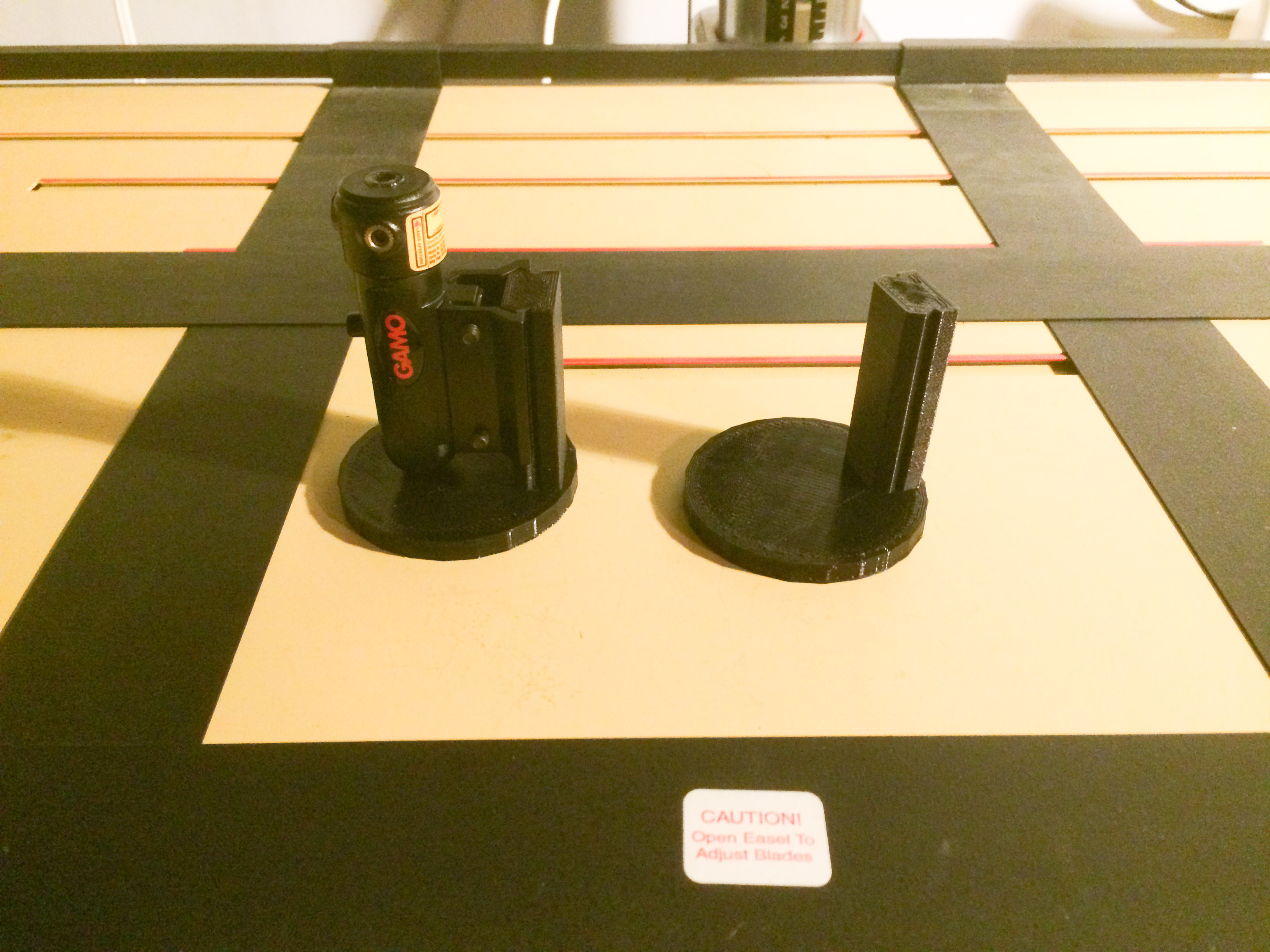
Years ago I found a laser sight that had a flat base. I’ve been using this to align my enlarger and it works very well. However I haven’t seen that model in years. Since I have frequently recommended building your own laser alignment tool I thought I would build a 3D printed stand to use the commonly available laser sights.
I have now released a 3D printed stand so you can build your own laser alignment tool.
Here are two scans of the Jobo Color Star 3000 manuals that I have.
One of the reasons I wanted to move to a full frame camera was to be able to use older manual focus lenses with the same field of view as they have on a film camera. For years I’ve had a Nikkormat FTN that I got when I bought a macro lens. For the price of the package, the camera was essentially free. The meter in the camera is off by about three stops, even with a battery adapter to work around the need for old mercury cells. But other than that it works perfectly. I really do enjoy using the all manual and mechanical camera. So over the years I have picked up a few manual focus lenses for the FTN. My intention was to be able to use them on the D800E when I bought that last year.
However reality and my plans didn’t align. Sure the lenses work on the camera, but I’ve found I can’t accurately focus them through the view finder with great consistency. The bright screens that Nikon uses on their autofocus cameras do not let you see critical focus. They also do not contain any manual focus aids like a split prism, or micro prisms. The conventional wisdom says you just use the focus confirmation dot, but I found that the focus dot is lit for quite a range of distances, so hitting focus just right is difficult. I actually get better results using the focus screen than the dot, as long as the subject is well lit and contrasty. One way I can get great results is to use LiveView. But that requires a tripod, and isn’t how I want to shoot much of the time.
When I first got the camera I looked for an alternate focus screen, but Nikon doesn’t offer them for the D800 cameras. And none were available from aftermarket suppliers at the time. So for the most part my manual focus lenses stayed with my old film camera, and really were not used that much.
A month ago it dawned on me that there might now be a focus screen available so I checked Google. There are some inexpensive ones on ebay. A bit of research showed very mixed results for these screens. There is also a company called FocusingScreen.com which has a range of screens for the D800E. They seem to have much better reviews. They are generally positive, so I decided it was worth the price premium to go with them. They also seem to offer higher quality screens based on original Nikon F6 screens. I’m not sure what modifications are made, but I assume it’s cutting some of the edge material to fit.
My favorite type of focusing screen is the K type, which contains a split prism surrounded by a ring of microprisms. But there doesn’t seem to be one with that configuration available for the D800. My FTN has a J type screen which is just micro prisms, and I have no issues focusing that. So I placed an order for the F6-J based screen. Ordering was bit odd, in that the PayPal checkout showed a tax. I checked with the company and it’s not really a tax, but rather the PayPal fees. So the price advertised on the site isn’t really the price you pay. Buyer beware. Other than that slight annoyance the order went smoothly.
The screen arrived about ten days after I ordered it, which apparently included a few days for them to make the screen.
Installation is documented on the FocusingScreen site. Their English is bit broken, and the instructions seem overly complicated at first. But the actual procedure is simple, and once you’ve done it you wonder why it took so many words to describe. I don’t want to responsible, so I’m not going to try to write up better instructions (and I’m not sure I can do a better job).
So does it work? It seems to, but it also seems to have messed up the metering. That’s not a surprise since the D800 meters through the focus screen (I’m sure that’s the main reason Nikon doesn’t want to support user replaceable screens). In subsequent posts I’ll try cover some of my tests with different lenses and seeing if I can get the metering adjusted to work consistently. I’m sure I’ll run into some issues. I just hope they aren’t show stoppers.
Bulbs for some enlargers are getting hard to find. The opal bulbs for the Durst 138S condenser heads have been out of production for many years. Occasionally new ones still turn up, but they are expensive and hard to find. If you have a bulb you probably hope it won’t die on you until you can find, and maybe afford, a replacement. This was my situation when I got my 138S. I had one bulb that I thought was original (turns out it isn’t, but it works well). When I eventually acquired a few of the original Durst Atlas Thorn bulbs I was hesitant to use them for fear of burning them out.
I had known for a while that a bulb run through a dimmer will last longer, but I wasn’t sure how much longer. Still I thought it would be prudent to try to extend the life, so I bought a Variac off of ebay. These are transformers that take your line voltage and bump it up or down in an adjustable fashion. Mine will take 120V and transform it to 0 to 130V. It plugs into the wall and has two regular sockets on it that you can plug your enlarger into. A big knob controls the output voltage. The scale on mine doesn’t exactly match the output voltage, but it’s very repeatable, so I just marked a few positions with the actual voltage. I recommend testing the voltage with a multimeter (only if you know how to use one safely with AC line voltages) as you don’t want to accidentally run the bulb at more than its rated voltage.
I found with the 500 Watt bulb that each 10V drop decreased the light output by 1/2 a stop. I settled on 110V as the maximum that I would run the bulb at to extend its life. For smaller prints I generally find the 500 Watt bulb too bright even at 110V, so I run it at 70 to 90V which gets me one to two extra stops of time for easier dodging and burning.
What I haven’t known was how much this could extend the life span of the bulb. However I just found the May/June 2000 issue of Photo Techniques magazine (I got a whole stack of these with the enlarger) which surprisingly has an article, “Optimize Enlarger Light Intensity” by Conrad R. Hoffmann, on reducing the light output with a Variac. In the notes section he gives the formula to calculate how much the lamp life is affected by the voltage. The formula is (Design Voltage / Actual Volatge)^12. Yes that’s the 12th power, so a minor voltage change can have a huge effect. For example running the lamp at 110V will give a 2.84 longer lamp life. That right there more than pays for the cost of the Variac, which ran about $100 and is what I see the bulbs going for recently. Running at 70V will increase the life by 644 times. That may mean you no longer need to worry about burning it out.
One thing to note is that the color temperature of the light drops as the voltage drops. Mine went from 2800K at 110V to 2300K at 70V. This will change the contrast some with VC paper. I think I lost about 1/2 a grade when dropping to 70V. I suppose you can use this to get intermediate grades if your filters aren’t fine enough for you.
I’ve been sporadically using the Sigma 35mm f/1.4 DG since March. I find that I generally like the rendering of the lens, but the auto focus leaves a lot to be desired. I’ve found that at closer distances I need stick to the center AF point, and even then it doesn’t nail the focus as well as my nikon lenses. When it does it’s very nice. When it misses, well there’s yet another lost image. Those lost images add up to a lot of frustration. Luckily I’m not trying to make a living with this lens. My solution has been to stop down and shoot at f/5.6 to f/8 if I’m just using it as a walk around lens. Not optimal, and certainly not taking advantage of the fast f/1.4 aperture.
I place an order for the Sigma USB Dock when it was announced. It finally arrived last week.
First Impressions
Opening the dock was uneventful. It comes with the dock, a body cap installed on the dock, a USB cable, minimal instruction manual and a warranty card.
The instructions do provide you with a link to download the application, but I missed it the first time looking though the sheet. I eventually found it with a search, but in here it is in case you are looking too: http://www.sigma-global.com/download.
Once installed on my mac the software found the dock without issue. Mounting the dock to the lens was not as smooth. When I first tried I followed the alignment marks on the dock and the lens, but the dock didn’t want to turn. I looked it over a few more times and eventually concluded it must just be tight, so I applied a bit more pressure. It mounted, but it was far from smooth. Not a great first impression. After taking it on and off, which is something you will need to do often to calibrate the lens, it is now much smoother.
The software immediately recognized the lens and offered to load the latest firmware onto it. This completed in a few minutes.
Customizing the Focus Settings
Sigma doesn’t provide written documentation that I have found. However they do have a basic overview video at http://vimeo.com/64665246.
The Sigma 35mm DG is a pretty simple lens and doesn’t have some of the modes the other lenses have such as focus limiters or image stabilization. So the options of what the Dock can set are limited.
Pressing the Customize button you have only one choice, which is the Focus Setting button. This brings you into the focus setting screen where you can configure how the lens focuses at each of four different distance ranges.
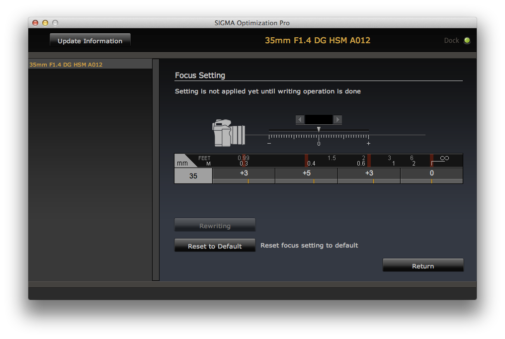
I haven’t found clear instructions on how best to determine the correct values. I wish the video had covered that a bit. But with a whole lot of trial and error I was able to get the values determined for my lens, which are shown in the image.
I basically set the focus at the distance shown on the chart and positioned a high contrast target so it was in focus at the point. Then I pressed the AF-ON button and took a picture. If it wasn’t sharp I used LiveView to get a feel for which way the lens needed to be turned to achieve focus. I then tried an adjustment. I frequently overshot and need to redo each position several times. This took me about an hour. Remember each adjustment requires you to take the lens off the camera and mount it to the dock. Then you navigate through the software to get back to the Focus Setting page. If I had a zoom lens I can see being very frustrated by having to adjust 16 different zones.
Results?
Well it’s only been a few days, and I haven’t taken the system out for a real trial run. But I have made lots of tests around the house.
The first thing I noticed is I can now use the side AutoFocus points and they seem as accurate as the center. I suspect this is a result of the firmware, but I didn’t think to do a before and after test.
The lens is also much more accurate in the closer distances. I can shoot with confidence wide open, which is really nice since the image is so good wide open with this lens. I’ve had to resort to Live View in the past to get accurate focus in the past.
Conclusion
I’ll be testing things out more over the rest of the summer. But it looks like the $59 fixed up my lens. I’m still a bit annoyed that it wasn’t perfect out of the box, but in the end I suspect that I’ve got a better match for my camera than if I had sent just the lens back to Sigma for a new firmware and calibration.
I think this process will get old quickly with a zoom lens or two. If Sigma just put a USB port directly on the lens I can see this being much easier as you could avoid taking the lens off the camera each time.
There are endless arguments about whether condenser printing or diffusion printing is best. Most of my experience is with diffusion printing with various color enlargers and most recently with the Ilford 500 head on an Omega D5. I tried the condenser head on the Omega, but not enough to gain an appreciation for it.
The Durst 138S has an excellent set of condensers. With the new enlarger I got a full set of the T condensers (T indicates they are coated).
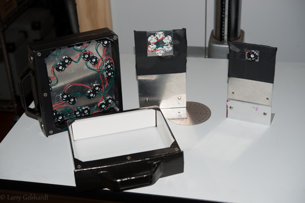
Three LED Light sources for the Durst 138S.
From the left 1) Variable Contrast diffusion, 2) Variable Contrast condenser, 3) point light
When I first got the Durst I didn’t have any choice but to print my 5×7 negatives with the condensers. I was able to get good results and found that the conventional wisdom on the subject is generally true. They really do print the same negative with more contrast. Prints do seem slightly sharper. The grain is better resolved. Scratches and dust on negatives is more apparent. But the conventional wisdom is wrong that a diffusion enlarger means you don’t need to spot as much. Diffusion still shows the dust, and it must still be taken care of.
The biggest issue I had with the condenser setup is that I can’t use pencil masking techniques. This is due to the fact the condenser setup relies on focusing an image of the light bulb at the nodal point of the lens. By adding an opaque mask above the negative you get some very uneven illumination since the condensers can no longer focus on the lens. Also, I lost the ability to finely adjust the contrast grade with VC papers, due to the use of VC filters only coming in 1/2 grade increments. This last part wasn’t much of an issue, but the loss of masking techniques was going to impact my printing.
So I built a diffusion light source for the enlarger, which is documented in a few posts. This is an LED diffusion head that has both green and blue LEDs for contrast control. This gave me the ability to print negatives with diffusion if I wanted to mask, but if I wanted the sharpness of the condensers I had to go back the old filtration control method with the hot tungsten bulb.
Another issue with the Durst 138S system is that it relies on large discontinued Opal bulbs. I have a few in various wattages now, and I found a PH/303 500watt bulb that works pretty well. The Opal bulbs are expensive and I doubt I’ll be able to find replacements as they get used up. The PH/303 runs pretty hot and requires a blower, which is a bit loud.
LED Condenser Light Source
I decided to build a head to get the advantages of the condensers along with the variable contrast control of the green and blue LEDs. I replaced the Opal bulb with a piece of milk glass that fits in the heat absorbing glass tray. Behind this I built an LED source with three green and three blue LEDs with the same specs as the ones used in the earlier head I built. I arranged these in a ring, alternating colors, on a piece of aluminum plate screwed to some aluminum angle iron. A few holes allow it to mount to the movable stage in the Durst head using the existing thumb screws. The plate also acts as heat sink. The LEDs were glued down with Arctic Alumina heat sink compound.
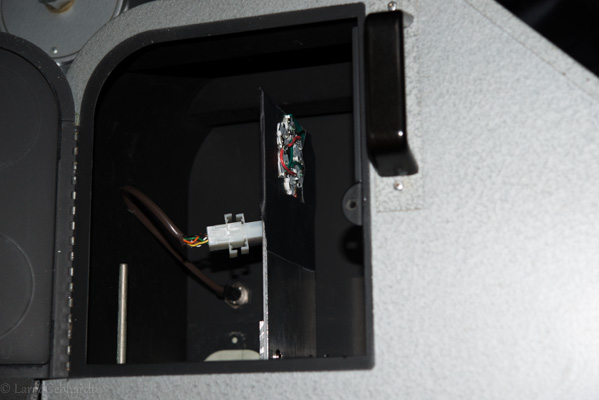
The Variable Contrast light source installed in the enlarger. Note the cable setup with a DIN plug mounted on the enlarger head wall and the quick connect plug on the light source.
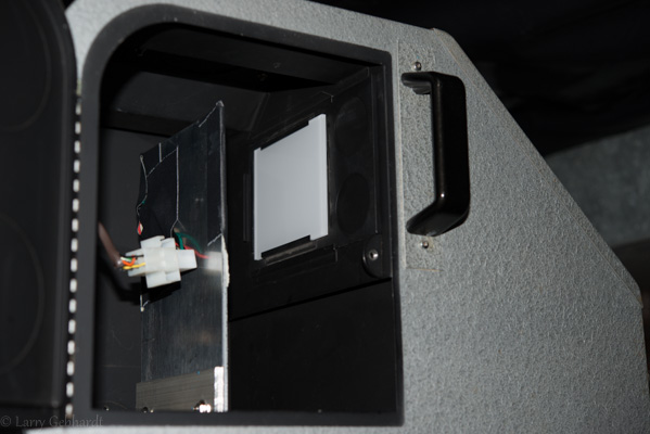
Another view of the VC light source showing the opal glass installed in the heat absorbing glass holder. Milk plexiglass works just as well here.
I also installed a matching DIN connector in the body of the Durst light chamber so I can simply plug one of the cables used for the diffusion head into this and reuse my controller and the LED drivers.
I’ve only printed a few negatives with this system, but in testing it works very well. The light source is as even as the original bulb (corners are 1/4 of a stop dimmer than the center), and contrast control works as it should. Because of the efficiency of the condenser design it’s only a 2/3 stop slower than the diffusion head, even though it’s using 1/4 of the LEDs. I’m not sure what else I could ask for.
LED Point Light Source
The Durst has an optional point source lighting system, which I haven’t used or seen. It occurred to me that while I was messing around with LEDs that I could build one with a single LED, since they are very small (almost a perfect point) and very bright. I took a single CREE High Noon LED that I know gives a very good light for printing on VC paper with filters. I mounted this on a similar place of aluminum as I had for the other source.
This is used without the diffusion glass in the heat absorbing tray. The Durst system comes with controls to adjust the position of the bulb in three dimensions. Once I figured out how to position the LED I was able to get very even coverage over the whole frame. Every time you adjust the enlarger height you need to reposition the bulb. I now appreciate how well the Durst controls work for this.
So how does it work? Well you need to use contrast filters again since it’s a single white light. The single LED used as a point source is several stops brighter than the other light sources. It’s so bright I needed to add a neutral density filter under the lens. With a point source setup you need to use the lens wide open, so you can’t adjust the brightness using the aperture ring.
I printed the same image with grass that I used to try out the diffusion head. First print was very sharp, but odd looking. Took me a while to realize it was the pattern from the anti-newton glass in the negative holder. I removed the glass and made another print. This looked good. The point source is much sharper than the diffusion head and quite a bit more contrasty. It also shows every little flaw in the negative. There are a few odd areas that are on the negative and can be seen with a good loupe. These are barely perceptible on the diffusion print, but are almost glaring on printed with the point light source.
I don’t have enough prints made with this setup to know if I’ll keep using it. But I can see how it could be really interesting with some grainy 35mm film and large enlargements. Should be very sharp, and have clearly defined grain. I plan to experiment.
Conclusion
I now have three different options that all work well in the Durst 138S. I can use the same F/stop based controller for them all, and switching them takes only minutes. I can now choose the best lighting type for each image or printing situation.
What’s next? Well I may buy an LED star that has a green and blue LED in very close proximity. This might allow me to have a variable contrast point source. It’s possible thought that even a few mm offset would not align correctly. It will run about $20 to test that out. I also plan to spend more time making prints and less making enlarger parts.
Over the weekend I got a box built for the controller and a separate one for the power supply. They are separate because I wanted to be able to move the unit around so it could be in a comfortable location. With the power supply, relay, safelight plugs and the LED drivers it was just too large. So I built a really ugly box out of sheet aluminum for the power supply. And I used a simple project box from Radio Shack to mount the Arduino with the keypad and display in. They are connected by an 8 conductor wire with RJ45 connectors (ethernet jacks and cable). This is nice and flexible, and since there’s very little power drawn by the controller it should be fine over the thin wire. Once I give the box a nice coat of hammered silver finish I’ll post some pictures so you all can laugh at my sheet metal skills.
I made my first print tonight using the system. It was a negative I took at lunch when the rain stopped (mostly) for a few minutes.
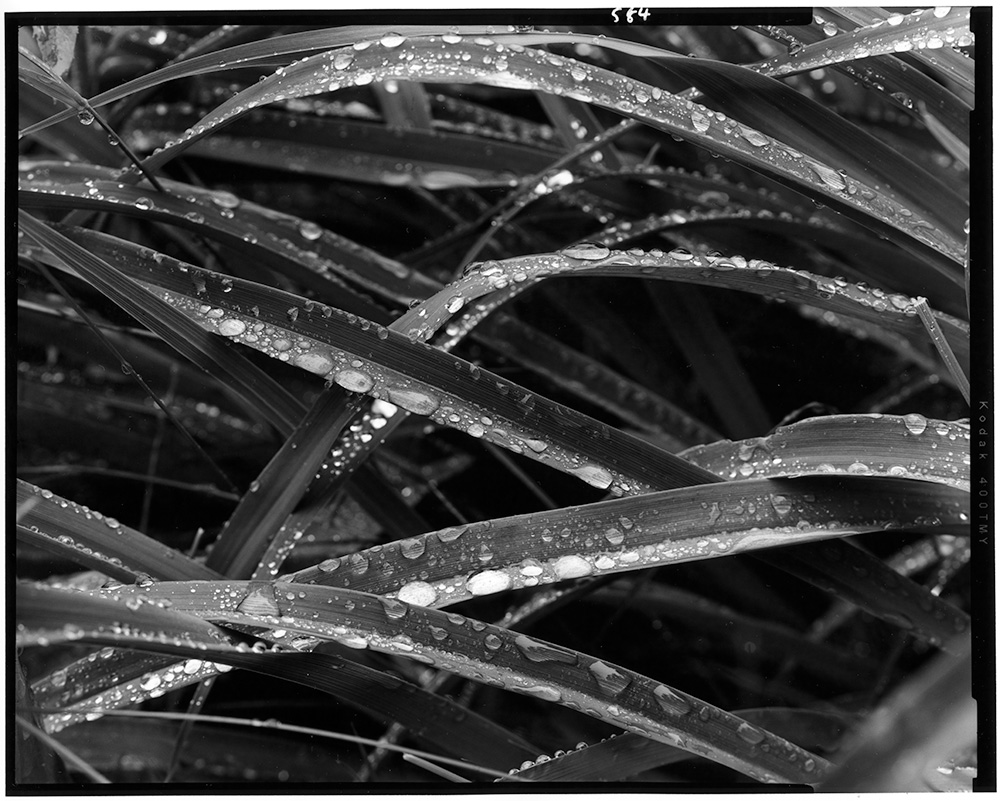
Shot on 4×5 T-Max 400 with a 210mm Macro Sironar and developed in Pyrocat HD in a Jobo Expert Drum. Printed on cheap Adorama RC paper.
The print is a straight print at an ISO Exposure Scale of 100 (grade 2). Despite the RC paper it looks really nice.
The head is fast as it’s setup. I needed to stop down to f/11 for the print and it was a 6 second exposure. I think this is over a stop faster than the condenser head, but I haven’t measured it. For small prints like this I want to build in a way to dim the lamps some more. That will require some changes to the code.
But so far everything worked well, except the test print mode. I screwed something up in that section of the code, and I realized as I went to use it that I had never tested it. So back to the editor it goes.
I’ve got a partial metal box made for the power supply and the LED drivers. This will also have relay to control the safe lights, and an additional power outlet that’s on opposite the safe lights. So this could also be used to drive a traditional enlarger. The box isn’t anything to look at right now, but once I make a top it’ll be electrically safe. I’ll post some pictures after it’s a bit more complete. At least it now holds all the parts together which allows me to test the system out.
I made some code changes to support calibration of different papers. I started with the idea of calibrating to the traditional paper grades, 00, 0, 1, 2, 3, 4, and 5; but there are really no standards for theses. And since they cover a range of contrasts it made programming the system rather confusing. So I settled on using the ISO system. This is easily measured using a simple densitometer and graph paper. It’s also fully supported by the BTZS Plotter app, which I use for testing.
The Variable Contrast Printing Manual by Stephen G. Anchell gives a good overview of how this works.
Papers will be eventually read off of an SD card, but for now I’ve been programming a default paper.
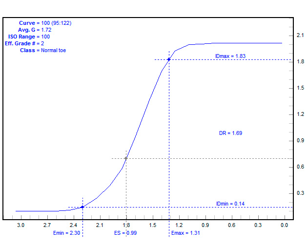
For testing I started by just running a simple test where as I increased the brightness on the soft LEDs I decreased the brightness on the hard LEDs. I kept the total at 217 (out of 255) on the PWM pins for the Arduino. This value was chosen because 217 is just below the cut off where the BuckBlock LED drivers start to flicker as they dim past this (0 is fully on at 1 amp, and 255 is fully off). I made exposures through a step wedge to arrive at this curve:
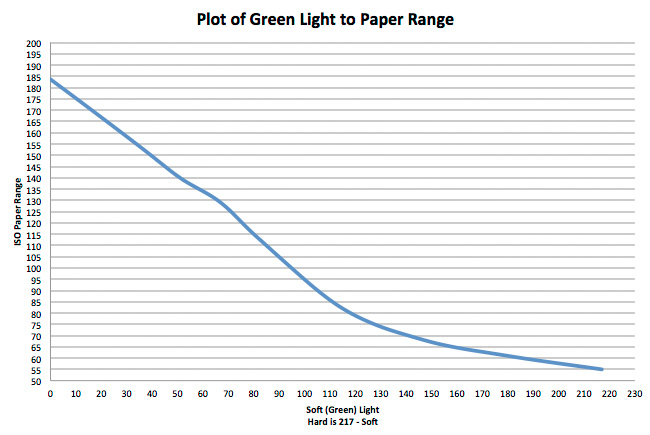
From this curve I reprogrammed the default paper curve in the Arduino code. This was done by looking up the grade I wanted on the vertical axis and finding the correct light ratio. I then reran the test strips at:
55 (Grade 4.x, as high as it goes on my paper and developer)
65 (Top of Grade 4)
80 (Top of Grade 3)
100 (Grade 2)
120 (Grade 1)
140 (Top of grade 0)
160 (Grade 0)
I could have run a strip at 180, but I never print this low and the Ilford MGIV has a really lumpy curve at this point, so I don’t really plan on using it. I would reduce my negative or change paper developers before printing with pure green light.
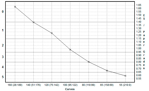
Once these curves were put in BZTS Plotter I got this graph which shows that the system is working pretty well. I could tweak things to make it more linear, but it tracks better than any other head I have used. Now I should know easily how much contrast I will get out of any change, and by reading the negative should be able to zero in on a decent starting contrast easily. Once the system is packaged up I’ll make more accurate curves for each paper I plan to use. That will let me switch papers easily since an ES of 100 should print with the same contrast on both papers (of course there will be visible differences, but the overall contrast should be the same).
The chart shows the input grade on the bottom axis, and the calculated grade on the vertical axis in both ISO Exposure Scale and traditional paper grades.
Currently I have the system setup to allow changes in 5 ES increments. This seems like a good compromise between precision and keeping the system easy to profile. I’m also not sure if a 1 ES change would even be noticeable, or repeatable between exposures.
Next I will solder up a prototype board. I’ll test it an then decide if I need any changes before committing to designing and ordering a few printed circuit boards.


Some small wild flowers shot in the backyard. Took the opportunity to test out three very different lenses to get close up shots of these small flowers. Used a Nikon 60mm f/2.8 AFS Macro, a 120mm f/4 Mamiya Macro (w/adapter) and a 35mm f/1.4 Sigma DG lenses on a Nikon D800E.
The Sigma 35mm isn’t a macro lens, but it does focus fairly close up. But given the short focal length is doesn’t have that much magnification. But it produces a very nice look, which I like better in many cases than a pure macro. No real conclusions, other than I like all three lenses.