Equipment

One of the reasons I wanted to move to a full frame camera was to be able to use older manual focus lenses with the same field of view as they have on a film camera. For years I’ve had a Nikkormat FTN that I got when I bought a macro lens. For the price of the package, the camera was essentially free. The meter in the camera is off by about three stops, even with a battery adapter to work around the need for old mercury cells. But other than that it works perfectly. I really do enjoy using the all manual and mechanical camera. So over the years I have picked up a few manual focus lenses for the FTN. My intention was to be able to use them on the D800E when I bought that last year.

However reality and my plans didn’t align. Sure the lenses work on the camera, but I’ve found I can’t accurately focus them through the view finder with great consistency. The bright screens that Nikon uses on their autofocus cameras do not let you see critical focus. They also do not contain any manual focus aids like a split prism, or micro prisms. The conventional wisdom says you just use the focus confirmation dot, but I found that the focus dot is lit for quite a range of distances, so hitting focus just right is difficult. I actually get better results using the focus screen than the dot, as long as the subject is well lit and contrasty. One way I can get great results is to use LiveView. But that requires a tripod, and isn’t how I want to shoot much of the time.

When I first got the camera I looked for an alternate focus screen, but Nikon doesn’t offer them for the D800 cameras. And none were available from aftermarket suppliers at the time. So for the most part my manual focus lenses stayed with my old film camera, and really were not used that much.

A month ago it dawned on me that there might now be a focus screen available so I checked Google. There are some inexpensive ones on ebay. A bit of research showed very mixed results for these screens. There is also a company called FocusingScreen.com which has a range of screens for the D800E. They seem to have much better reviews. They are generally positive, so I decided it was worth the price premium to go with them. They also seem to offer higher quality screens based on original Nikon F6 screens. I’m not sure what modifications are made, but I assume it’s cutting some of the edge material to fit.

My favorite type of focusing screen is the K type, which contains a split prism surrounded by a ring of microprisms. But there doesn’t seem to be one with that configuration available for the D800. My FTN has a J type screen which is just micro prisms, and I have no issues focusing that. So I placed an order for the F6-J based screen. Ordering was bit odd, in that the PayPal checkout showed a tax. I checked with the company and it’s not really a tax, but rather the PayPal fees. So the price advertised on the site isn’t really the price you pay. Buyer beware. Other than that slight annoyance the order went smoothly.

The screen arrived about ten days after I ordered it, which apparently included a few days for them to make the screen.

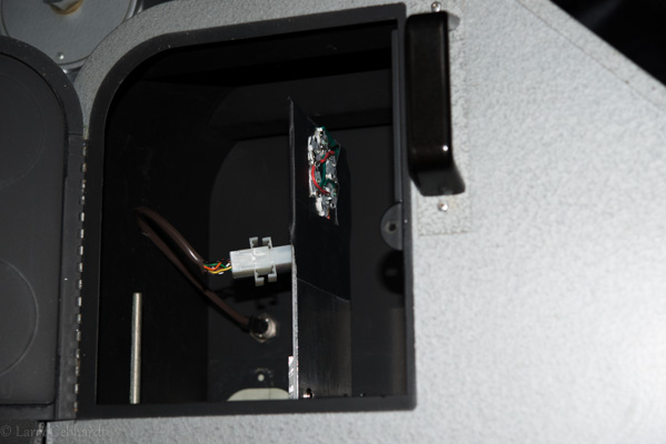
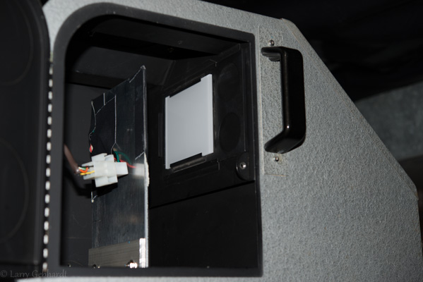
Installation is documented on the FocusingScreen site. Their English is bit broken, and the instructions seem overly complicated at first. But the actual procedure is simple, and once you’ve done it you wonder why it took so many words to describe. I don’t want to responsible, so I’m not going to try to write up better instructions (and I’m not sure I can do a better job).

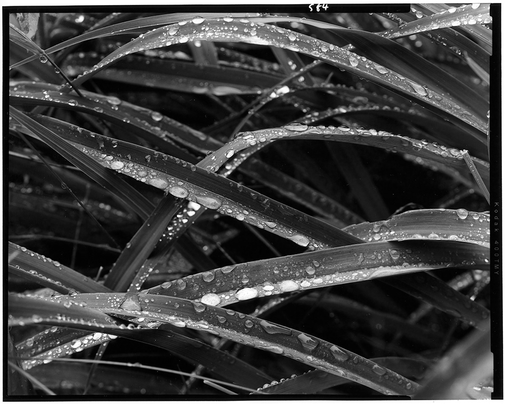
So does it work? It seems to, but it also seems to have messed up the metering. That’s not a surprise since the D800 meters through the focus screen (I’m sure that’s the main reason Nikon doesn’t want to support user replaceable screens). In subsequent posts I’ll try cover some of my tests with different lenses and seeing if I can get the metering adjusted to work consistently. I’m sure I’ll run into some issues. I just hope they aren’t show stoppers.

There are endless arguments about whether condenser printing or diffusion printing is best. Most of my experience is with diffusion printing with various color enlargers and most recently with the Ilford 500 head on an Omega D5. I tried the condenser head on the Omega, but not enough to gain an appreciation for it.

The Durst 138S has an excellent set of condensers. With the new enlarger I got a full set of the T condensers (T indicates they are coated).

20130712-202857

Three LED Light sources for the Durst 138S.
From the left 1) Variable Contrast diffusion, 2) Variable Contrast condenser, 3) point light

When I first got the Durst I didn’t have any choice but to print my 5×7 negatives with the condensers. I was able to get good results and found that the conventional wisdom on the subject is generally true. They really do print the same negative with more contrast. Prints do seem slightly sharper. The grain is better resolved. Scratches and dust on negatives is more apparent. But the conventional wisdom is wrong that a diffusion enlarger means you don’t need to spot as much. Diffusion still shows the dust, and it must still be taken care of.

The biggest issue I had with the condenser setup is that I can’t use pencil masking techniques. This is due to the fact the condenser setup relies on focusing an image of the light bulb at the nodal point of the lens. By adding an opaque mask above the negative you get some very uneven illumination since the condensers can no longer focus on the lens. Also, I lost the ability to finely adjust the contrast grade with VC papers, due to the use of VC filters only coming in 1/2 grade increments.  This last part wasn’t much of an issue, but the loss of masking techniques was going to impact my printing.

So I built a diffusion light source for the enlarger, which is documented in a few posts. This is an LED diffusion head that has both green and blue LEDs for contrast control. This gave me the ability to print negatives with diffusion if I wanted to mask, but if I wanted the sharpness of the condensers I had to go back the old filtration control method with the hot tungsten bulb.

Another issue with the Durst 138S system is that it relies on large discontinued Opal bulbs. I have a few in various wattages now, and I found a PH/303 500watt bulb that works pretty well. The Opal bulbs are expensive and I doubt I’ll be able to find replacements as they get used up. The PH/303 runs pretty hot and requires a blower, which is a bit loud.

LED Condenser Light Source

I decided to build a head to get the advantages of the condensers along with the variable contrast control of the green and blue LEDs. I replaced the Opal bulb with a piece of milk glass that fits in the heat absorbing glass tray. Behind this I built an LED source with three green and three blue LEDs with the same specs as the ones used in the earlier head I built. I arranged these in a ring, alternating colors, on a piece of aluminum plate screwed to some aluminum angle iron. A few holes allow it to mount to the movable stage in the Durst head using the existing thumb screws. The plate also acts as heat sink. The LEDs were glued down with Arctic Alumina heat sink compound.

20130712-213407

The Variable Contrast light source installed in the enlarger. Note the cable setup with a DIN plug mounted on the enlarger head wall and the quick connect plug on the light source.

20130712-213430

Another view of the VC light source showing the opal glass installed in the heat absorbing glass holder. Milk plexiglass works just as well here.

I also installed a matching DIN connector in the body of the Durst light chamber so I can simply plug one of the cables used for the diffusion head into this and reuse my controller and the LED drivers.

I’ve only printed a few negatives with this system, but in testing it works very well. The light source is as even as the original bulb (corners are 1/4 of a stop dimmer than the center), and contrast control works as it should. Because of the efficiency of the condenser design it’s only a 2/3 stop slower than the diffusion head, even though it’s using 1/4 of the LEDs. I’m not sure what else I could ask for.

LED Point Light Source

The Durst has an optional point source lighting system, which I haven’t used or seen. It occurred to me that while I was messing around with LEDs that I could build one with a single LED, since they are very small (almost a perfect point) and very bright. I took a single CREE High Noon LED that I know gives a very good light for printing on VC paper with filters. I mounted this on a similar place of aluminum as I had for the other source.

This is used without the diffusion glass in the heat absorbing tray. The Durst system comes with controls to adjust the position of the bulb in three dimensions. Once I figured out how to position the LED I was able to get very even coverage over the whole frame. Every time you adjust the enlarger height you need to reposition the bulb. I now appreciate how well the Durst controls work for this.

So how does it work? Well you need to use contrast filters again since it’s a single white light. The single LED used as a point source is several stops brighter than the other light sources. It’s so bright I needed to add a neutral density filter under the lens. With a point source setup you need to use the lens wide open, so you can’t adjust the brightness using the aperture ring.

I printed the same image with grass that I used to try out the diffusion head. First print was very sharp, but odd looking. Took me a while to realize it was the pattern from the anti-newton glass in the negative holder. I removed the glass and made another print. This looked good. The point source is much sharper than the diffusion head and quite a bit more contrasty. It also shows every little flaw in the negative. There are a few odd areas that are on the negative and can be seen with a good loupe. These are barely perceptible on the diffusion print, but are almost glaring on printed with the point light source.

I don’t have enough prints made with this setup to know if I’ll keep using it. But I can see how it could be really interesting with some grainy 35mm film and large enlargements. Should be very sharp, and have clearly defined grain. I plan to experiment.

Conclusion

I now have three different options that all work well in the Durst 138S. I can use the same F/stop based controller for them all, and switching them takes only minutes. I can now choose the best lighting type for each image or printing situation.

What’s next? Well I may buy an LED star that has a green and blue LED in very close proximity. This might allow me to have a variable contrast point source. It’s possible thought that even a few mm offset would not align correctly. It will run about $20 to test that out. I also plan to spend more time making prints and less making enlarger parts.

Over the weekend I got a box built for the controller and a separate one for the power supply. They are separate because I wanted to be able to move the unit around so it could be in a comfortable location. With the power supply, relay, safelight plugs and the LED drivers it was just too large. So I built a really ugly box out of sheet aluminum for the power supply. And I used a simple project box from Radio Shack to mount the Arduino with the keypad and display in. They are connected by an 8 conductor wire with RJ45 connectors (ethernet jacks and cable). This is nice and flexible, and since there’s very little power drawn by the controller it should be fine over the thin wire. Once I give the box a nice coat of hammered silver finish I’ll post some pictures so you all can laugh at my sheet metal skills.

I made my first print tonight using the system. It was a negative I took at lunch when the rain stopped (mostly) for a few minutes.

First Print

Shot on 4×5 T-Max 400 with a 210mm Macro Sironar and developed in Pyrocat HD in a Jobo Expert Drum. Printed on cheap Adorama RC paper.

The print is a straight print at an ISO Exposure Scale of 100 (grade 2). Despite the RC paper it looks really nice.

The head is fast as it’s setup. I needed to stop down to f/11 for the print and it was a 6 second exposure. I think this is over a stop faster than the condenser head, but I haven’t measured it. For small prints like this I want to build in a way to dim the lamps some more. That will require some changes to the code.

But so far everything worked well, except the test print mode. I screwed something up in that section of the code, and I realized as I went to use it that I had never tested it. So back to the editor it goes.


I’ve got a partial metal box made for the power supply and the LED drivers. This will also have relay to control the safe lights, and an additional power outlet that’s on opposite the safe lights. So this could also be used to drive a traditional enlarger. The box isn’t anything to look at right now, but once I make a top it’ll be electrically safe. I’ll post some pictures after it’s a bit more complete. At least it now holds all the parts together which allows me to test the system out.

I made some code changes to support calibration of different papers. I started with the idea of calibrating to the traditional paper grades, 00, 0, 1, 2, 3, 4, and 5; but there are really no standards for theses. And since they cover a range of contrasts it made programming the system rather confusing. So I settled on using the ISO system. This is easily measured using a simple densitometer and graph paper. It’s also fully supported by the BTZS Plotter app, which I use for testing.

The Variable Contrast Printing Manual by Stephen G. Anchell gives a good overview of how this works.

Papers will be eventually read off of an SD card, but for now I’ve been programming a default paper.

For testing I started by just running a simple test where as I increased the brightness on the soft LEDs I decreased the brightness on the hard LEDs. I kept the total at 217 (out of 255) on the PWM pins for the Arduino. This value was chosen because 217 is just below the cut off where the BuckBlock LED drivers start to flicker as they dim past this (0 is fully on at 1 amp, and 255 is fully off). I made exposures through a step wedge to arrive at this curve:

Light Ratio To Grade

From this curve I reprogrammed the default paper curve in the Arduino code. This was done by looking up the grade I wanted on the vertical axis and finding the correct light ratio. I then reran the test strips at:

55 (Grade 4.x, as high as it goes on my paper and developer)

65 (Top of Grade 4)

80 (Top of Grade 3)

100 (Grade 2)

120 (Grade 1)

140 (Top of grade 0)

160 (Grade 0)

I could have run a strip at 180, but I never print this low and the Ilford MGIV has a really lumpy curve at this point, so I don’t really plan on using it. I would reduce my negative or change paper developers before printing with pure green light.

Second Calibration Curve

Once these curves were put in BZTS Plotter I got this graph which shows that the system is working pretty well. I could tweak things to make it more linear, but it tracks better than any other head I have used. Now I should know easily how much contrast I will get out of any change, and by reading the negative should be able to zero in on a decent starting contrast easily. Once the system is packaged up I’ll make more accurate curves for each paper I plan to use. That will let me switch papers easily since an ES of 100 should print with the same contrast on both papers (of course there will be visible differences, but the overall contrast should be the same).

The chart shows the input grade on the bottom axis, and the calculated grade on the vertical axis in both ISO Exposure Scale and traditional paper grades.

Currently I have the system setup to allow changes in 5 ES increments. This seems like a good compromise between precision and keeping the system easy to profile. I’m also not sure if a 1 ES change would even be noticeable, or repeatable between exposures.

Grade 2


Next I will solder up a prototype board. I’ll test it an then decide if I need any changes before committing to designing and ordering a few printed circuit boards.

20130525-183450

I’ve been slowly making progress on the VC LED head. I choose to tackle this as two separate steps; the head and the controller. What you see here are the two pieces of the head resting on the baseboard of my Durst 138S. I choose this configuration to allow me to quickly switch from this diffusion light source back to the original condenser head. What I did was take two scratched condensers and removed the glass. One was a 240mm and I used it for the top part (bottom in the picture). Into this I drilled two holes on the front for 6pin Din connectors. On the inside I mounted a sheet of 1/4″ aluminum for a heat sink and support for the LEDs. This is held in place by the original Durst screws and some aluminum tubing over them cut to fit snuggly. In the other condenser shell I mounted a piece of 1/8″ translucent white plexiglass, which is held in place with white foam core around the edges. First I needed to cut some of the metal from shell since this was for a smaller 130mm condenser. A metal blad in a jig saw made quick work of this since the shells are aluminum.

The LEDs are Cree XP-E Green for the soft light and Cree XT-E Royal Blue for the hard light. There are 12 of each arranged in two banks. This arrangement was chosen based on the capabilities of the controllers I am using. I originally was going to go with a Mean Well 60-48D which could drive all 12 LEDs in each bank, but I found it didn’t dim quickly enough to allow the dimming feature to turn the lights on and off. After a bit of research I settled on using A009-D-V-1000 BuckBlocks, which offer a lot of options for control, and respond instantly to dimming commands. The only issue is they don’t have enough forward voltage to drive more than 6 or 7 of these high power LEDs.

I was originally only going to have one cable to feed power to the head, but I found out the hard way that each BuckBlock must have it’s own ground wire along with hot wire, so my 6pin Din connectors don’t have enough pins for all the needed wires. For reference when I hooked two of the controllers up with the negative wire as common when one was dimmed the excess current is fed into the other bank of LEDs. When I checked 2A were flowing through my 6 green LEDs (rated for 1A maximum). They still work, but I do wonder how much of their life I used up in the minute or two it took to figure out what was going on.

20130525-183532

Right now they are hooked up a bank of 4 10K potentiometers. This allows me to adjust the brightness of each bank for testing purposes. The head is even to less than 1/3 of a stop across most of the surface. The very corners are about 1/3 stop dimmer than the rest. Given the arrangement of the LEDs I can adjust (in software) to bring the far edges and corners up in relation to the center. Doing this gets me a very even light source. On the baseboard (factoring in lens falloff) it’s even to about 1/5 of a stop. I might be able to tweak this more, but it’s better than any of my other enlargers, though I haven’t made any prints with it yet.

20130525-183627

I think I may want to get some right angle connectors for the cables. I’d also like to get a more flexible wire for the cords. But other than that I am pretty happy with this first phase of the project.

I have also been experimenting with the Arduino based controller for all of this. The BuckBlocks can be controlled with a PWM signal and a simple 2N2222 transistor (see their data sheet for wiring diagram). This should make wiring up the system fairly easy. They also respond instantly this way from off  then to fairly dim up to full brightness.

I’m still working on the software and board design, but I’ve checked a preliminary version of the controller code into GitHub. This is based on William Brodie-Tyrrell’s F/Stop Timer. This is very preliminary, but I’m trying to get it working in both a split grade and integrated mode. Feel free to fork the code and send me a pull request if you want to add a cool feature.

I have been printing with the condenser head on my Durst 138S. I use Ilford multigrade filters in the filter drawer for contrast control. I like the sharpness of the grain that the condensers give, and there’s something satisfying about sliding the correct condensers into the slots, due I think to their heft and how well built the machine is. But, and there’s always a ‘but’, when I want to make use of a dodge and burn mask I can’t. This is an inherent limitation of the condenser system which essentially focuses an image of the light source (bulb) through the negative and into the center of the enlarger lens. This collimated light is what’s responsible for the perceived sharpness of the prints. But it means that adding a diffusion layer as needed by the dodge / burn / pencil masks breaks the design.

I tried various methods of diffusing the existing light, but the results were wither too dim for large prints, or too uneven. So I decided to build my own light source. I had used white LEDs to make a simple head before, which worked pretty well. It was simply a bank of high power LEDs and a constant current controller which plugged into a timer. I thought about rebuilding this to fit the Durst. But given it’s a 5×7 enlarger I can’t find contrast filters large enough to fit above the negative, and I wanted to avoid under the lens filters (partially since the current set isn’t big enough to fit under the 210mm lens I have). I also enjoyed being able to set the contrast in finer steps than 1/2 a grade when I was using an Ilford 500 head on the 4×5 Omega.

So I’ve decided to build a variable contrast head. This will use two colors of LEDs; green for the soft grades; blue for the hard grades. By varying the intensity between them I should be able to produce any grade between the two extremes.

Parts have been ordered, and I’ve been playing with the LEDs and controllers. I’ll post some updates soon.

I talked with a nice Sigma rep and he gave me the option of sending the lens and camera in to them and they would adjust the lens to match the camera. I thought about this for a bit and decided against it. The main reason was the cost. I could send the lens back to B&H for no charge, or I could pay to ship the lens and camera to Sigma. With insurance this was going to run around $65, and I would not have the use of the camera for a week or so. So I sent the lens back to B&H. If I was near the Sigma service center bringing it in would have been the easy choice.

Rather than wait for another possibly defective lens to arrive at B&H and then get to me, I called Hunt’s Photo in Manchester NH. They had a lens shipped up from the Boston store. Today I went and briefly tested it out. AF seemed accurate at all distances. So I bought the lens.

I went for a walk around the village with it once I got home to test it out. I have only briefly looked at the pictures, but in going through them I feel the AF performance is acceptable even at f/1.4 and all the distances I tried. This weekend I’ll take a little more time to see if AF fine tuning will help, but at first glance it’s working fine without it.

When I started the walk I remembered the opening conversation I had with the Sigma rep. He initially thought I was calling to report an issue with the side AF points not working. I explained the issue with distances and he dropped the subject of the side AF points. This was also mentioned by another person in this thread I started on photo.net. In theory Sigma will have a fix for this soon.

So I also tested out the side AF points on a few shots. I think my results on this are inconclusive. Some of the shots seem off a bit using the side AF points, and a few seem OK. I will need to do a more controlled study. But for the time being I can live with just using the central point and recomposing. It’s still better than my results with manual focus and a fast lens on this camera.

When I saw the early reviews for the Sigma 35mm f/1.4 DG lens I though it had a lot to offer me. 35mm is probably my favorite focal length for general photography. Reviews praise the lens for how sharp it is wide open. It also seems to have decent bokeh (out of focus rendering). I have been using a Rokinon 35mm f/1.4 lens on the D800E since I bought the camera last spring. I am really happy with the image quality of the Rokinon, but I have lots of trouble achieving perfect focus with it since it’s a manual focus lens and the D800E has a screen that’s not very good for manual focus. This really limits my use to the tripod and Live View focusing. So I ordered the Sigma, even though it was on back order.

Last Thursday it arrived. I quickly did some indoor focus tests and like all the other lens on this particular camera it seems I needed no Fine Tune focus adjustment. Cool. But my tests were done inside at close distances. We got some snow that evening and then is stopped midmorning Friday. I went out for a walk at lunch, despite the ugly gray sky. I brought a tripod to do a few tests to see if the lens was obviously decentered, and also just shot a lot of hand held shots around the village, since this is how I hope to use the lens much of the time. On Sunday I went to my brother’s house and shot a few pictures of his dog (and the rest of the family, but I won’t put them in this post), again hand held.

Upon review of the images I found some were perfectly in focus, and some were way off. I noticed the close up ones were good, and the more distant ones were soft. So I shot a lot of tests in the backyard and found that with the lens adjustment at 0 the auto focus was right on for close distances, but infinity was way off.  I adjusted for infinity which requires a -11 for the Auto Focus Fine Tune. Close up shots are now noticeably soft. I’m not sure what to make of this. Sigma will be making a USB dock and software to adjust the focus points, so maybe this is the solution. But it’s not available now, and I don’t know when it’s coming out. It also seems crazy that we need to spend more money to make our lens work as it should. I haven’t decided if I should send it back to B&H and wait for another copy to come in, or send it to Sigma for repair.

Here’re a few examples:

20130308-133945

Full image. Focus on hanging sign.

20130308-133945-2

Focus point

20130308-133945-3

Background that’s more in focus than focus point.

20130308-134214

Full sized shot of mailbox. Take fairly close up. Focus point on red flag on front.

20130308-134214-2

Focus point on red flag. I’d say it got pretty close.

20130310-144028

Close up shot with focus point on left eye. f/4

20130310-144028-2

Left eye. Again the close up focus is good.

There are a few more shots over on my SmugMug gallery. Most are at f/1.4 to show the focus errors more clearly. There are a few shot stopped down. It’s pretty amazing how well corrected this lens is at wide apertures. Over all I am pretty happy with the image quality. It’ll certainly take many more shots to learn the lens. But sadly it doesn’t look like I can trust the Auto Focus, so is it really any better than my manual focus Rokinon?