
I have just created a 3D printed model for a laser alignment tool. This allows you to attach a laser scope from a pistol in the vertical position and use it to align your enlarger or large format camera standards.
The model is at thingiverse and can be downloaded and printed. There are also companies that will print models for you, but I don’t have any recommendations on them.
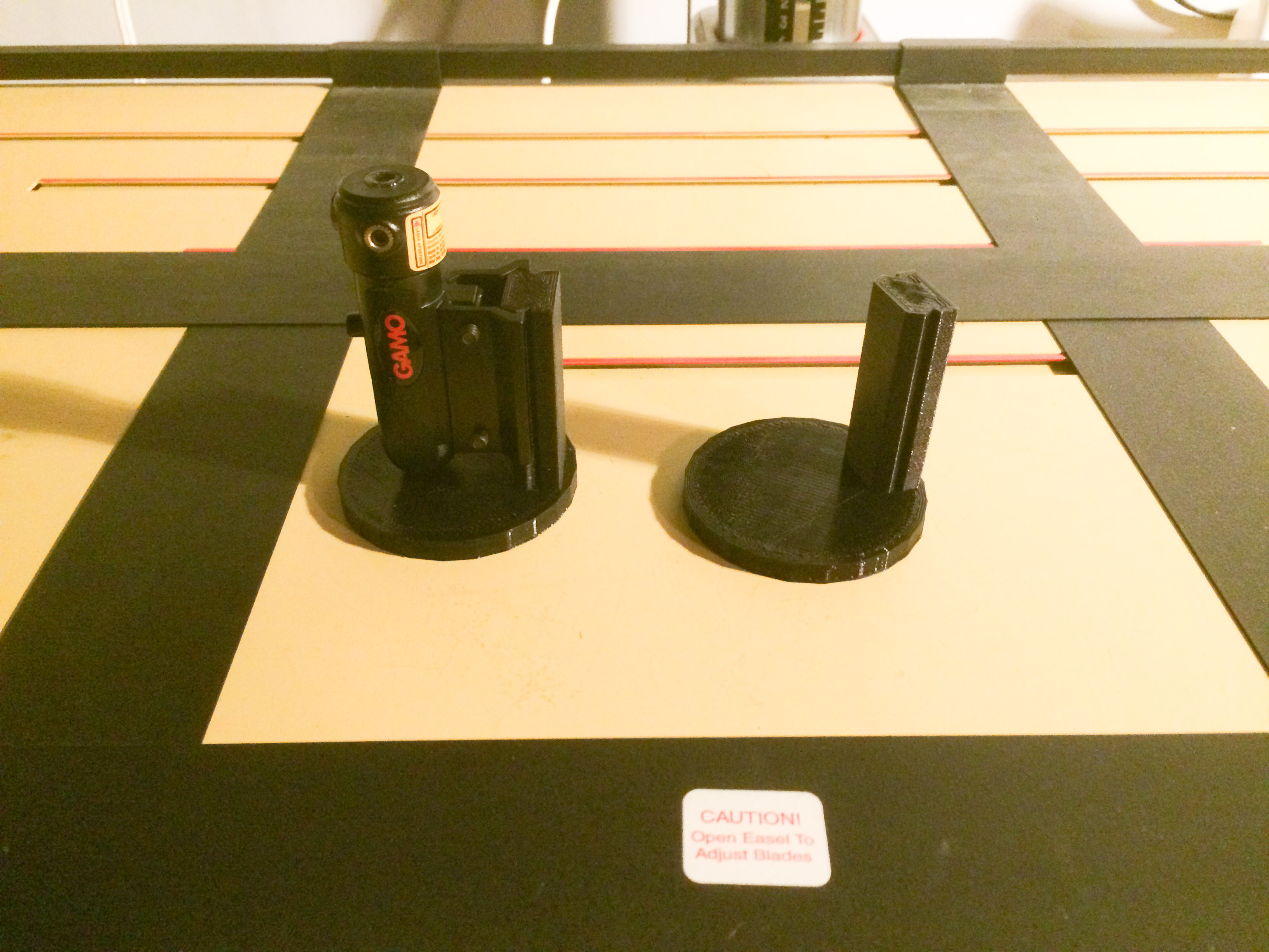
Alignment Tool with Laser on the left and plane stand as it came out of the printer on the right.
Once you have the part printed out you will need a laser sight for a pistol that clamps to an accessory rail. Make sure you get one which features adjustment screws to aim the laser. An inexpensive sight for an air-soft or pellet pistol will be fine. You can get a nice one for $17 at Walmart, or less online. You will also need a small piece of mirror, which you can get at the hardware store. you might want to have the sharp edges dressed to make it safer to handle.
Start by clamping the laser sight onto the dovetail rail with the laser pointing up. Leave enough of a gap to turn the laser on if the switch is on the back. The laser aperture should be approximately centered, but it doesn’t make too much difference if it’s not.
Note: avoid letting the beam hit you in the eye.
Raise the enlarger head close to the maximum height (it will be more accurate this way). Place the mirror on the negative stage. Remove the lens from the enlarger.
Place the alignment tool on the baseboard, or better yet the easel, and turn the laser on. Position it so the beam hits the mirror and reflects back down. Turn the alignment tool on the base board. If the beam is perpendicular to the base the reflected dot will stay in one spot. If it circles a spot as you rotate you will need to adjust the set screws on the sight. This is the hardest part, but it’s still pretty easy if you do it in several iterations. First find the center position of the circle the beam makes as you rotate the tool. Turn the set screws to bring the beam to that center spot. Keep rotating, adjusting and checking until the reflected beam hardly moves at all.
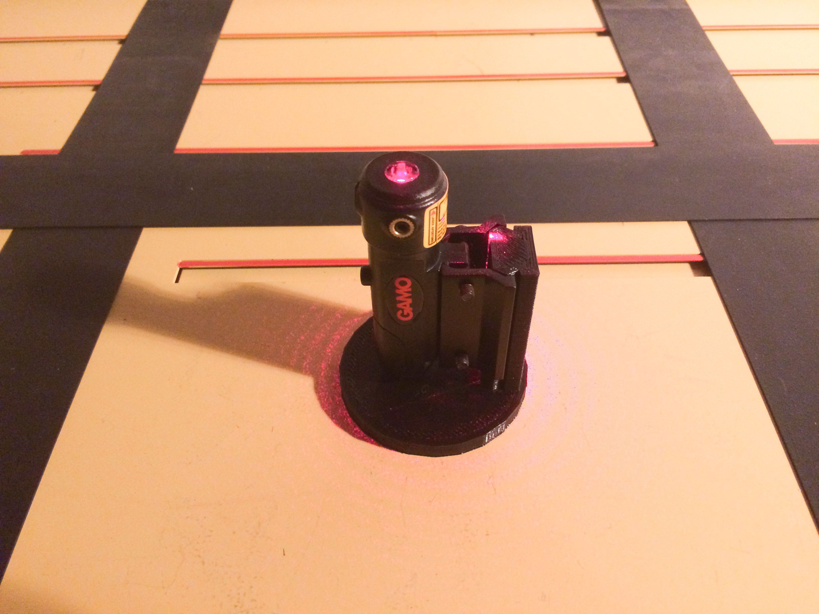
Not quite there
At this time you should adjust you negative stage or baseboard to make the beam reflects back on itself. If you can rotate the tool and the beam always reflects back into the hole it emerged from than the two planes are parallel and the laser is perpendicular to the tool.
You should also align the lens stage. This is easily done if you assume the front filter ring of the lens is aligned to the optics of the lens (probably a safe enough bet). Simply hold the mirror flush against the lens filter ring and adjust the stage as you did with the negative stage.
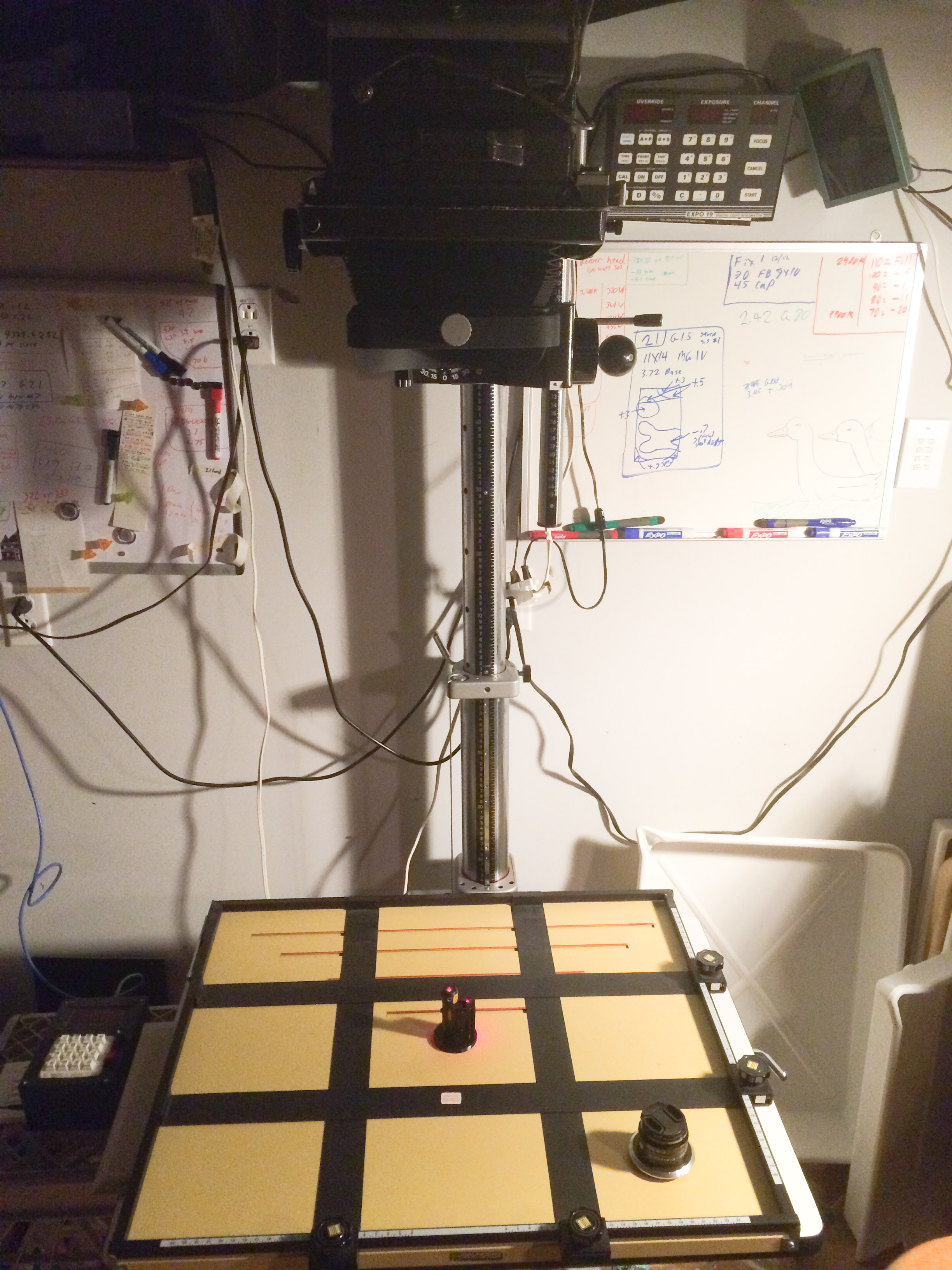
In use on Durst 138S. Mirror is in the negative carrier.
Pingback: Laser Alignment Tool – 3D printed stand | Tripping Through The Dark
So this process is to ensure your mirror (or negative in the carrier) is level with the baseboard for your print? I have not had very much experience in the darkroom, and did not know that one can “Turn the alignment tool on the base board” — so I will have to look out for that next time.
You rotate the (Laser Alignment) Tool 360 degrees to ensure the “two planes (mirror and baseboard) are parallel and the laser is perpendicular to the tool”.
Ok, apparently I’m still trying to understand… are there adjustments on the baseboard to ‘level’ it? It sounds like you are simply adjusting the laser sight on the 3D printed mounting bracket?
“Turn the (laser) alignment tool on the base board. If the beam is perpendicular to the base the reflected dot will stay in one spot. If it circles a spot as you rotate you will need to adjust the set screws on the (laser) sight”
There are two things going on. The first is you need to make the alignment tool so the beam is perpendicular to the base. The best way I know is to rotate it. If the reflected spot (or just a spot on the ceiling) does not move as the tool is rotated then the beam must be perpendicular. I use the adjustments on the sight to adjust the beam.
The next is using the tool to align the enlarger. There you don’t need to rotate the tool, but adjust all the enlarger parts to return the reflected spot to the laser aperture.
Hope that helps.
That does help, thank you. I just found a commercial product for this from Versalab which has a little target board around the opening of the laser which makes sense to me… so you can see just how far off you are in alignment until the laser reflect back (from the mirror in the negative carrier holder) into itself. A bit more expensive for the commercial version. (Which is certainly the truth for ‘print washers’ too!)
http://www.versalab.com/server/photo/products/parallel.htm
http://www.freestylephoto.biz/20240-Versalab-Parallel-Enlarger-Laser-Alignment-Gauge
The Versalab is certainly a premium product compared to this. It may seem expensive, but my guess is they are not making much money on it given the probable small sales volume.
You could easily put a target on top of this one too, but I don’t find it’s needed at all. If I’m not getting a reflection back to at least the area around the laser emitter it’s not close enough. If I am the target won’t add much value.
Looks intriguing. I don’t have a 3d printer but looking at a few local services.
Do you have suggestions as to material?
Also, the services seem to charge based on cubic cm of material. Do you know what that is for your design?
Thanks.
I printed mine use PLA, but I’m sure ABS would be fine too. It’s not a high stress part so almost any material should work.
I’m not sure on the volume. Netfabb reports about 34cm^3, but that’s the piece volume, which doesn’t need to be 100% filled. I print simple parts like this with 10% infill, and a few solid layers on the surface. To print like that should use 293 cm of 3mm filament, which is about 21cm^3 of plastic. Hope that helps figure out the pricing.
I found a somewhat local person that provided an estimate based on the stl file. His initial estimate assumes 40% infill. I’m not sure if 40% is adequate from a strength and rigidity perspective or if I should go to 60%.
The areas I’m most concerned about is the joint where the perpendicular piece meets the base and the clamping surface.
He offers both ABS and PLA. From my admittedly basic research, sounds like ABS might be best.
BTW, his quote was $5 for the piece plus $5.25 for shipping. Which sounds very reasonable to me.
I think even 40% is overkill for the infill, but it won’t take too much extra time to print it since it’s a small piece. I’ve found PLA is adequate for parts like this. It doesn’t flex much, though it is brittle. I took an early prototype that had the vertical column a bit too short and tried to break it. It took a lot of force before it broke, and when it did nothing was bent. The column came off of the base, along with some of the top of the base, so you are correct on the failure point. The two pieces could be put back together and it didn’t look like it had even snapped. That was with 10% infill and PLA. Certainly nothing wrong with going to 40% however, and for the price he’s offering I would jump at it.
The one I had made came today and, to my eye, look pretty good. Not sure how to insert a photo but in reality looks just like the one above. Mine came from http://www.oberdas3d.com and was just over $10 for qty 1 including shipping.
Now to get the laser sight.
That’s quite a deal. I’m not sure how they make money at that rate. As long as it doesn’t wobble and is close to straight it should be good. You’re the first one I know of to pull down my design and get it printed. It’s a pretty cool thought that it’s now a possibility.
They seem to be just fine. I still have to align the sight to the base. As I see it, the rotation approach will only work in the laser is exactly in the center of the base. Mine appears to be, but not sure. Do laser sights have a predetermined and consistent offset from the “rail” attachment point?
What I’ll do is drop a plumb bob from a tall ceiling over a level (or made level) surface. Then align the laser to that.
Here’s a link to the guy I used to build these: http://www.oberdas3d.com
I plan to have him make some hard-to-find slip on lenscaps next.
The rotation approach doesn’t rely on the laser being in the center. The returned spot will be relative to the laser source, not an absolute position. There is no standard for the laser relative to the rail, at least in the cheap sights.